The gas generator core of the Artouste is very similar of the nimbus , minus the axial compressor stages. The engine was designated 'Airborne Auxillary Power Plant AAPP', and was designed to supply compressed air for main engine starting and to drive a 40kVA alternator. The unit was mounted in the starboard wing root of an RAF Victor Bomber.
Specifications:
Single stage centrifugal compressor, pressure ratio 3.6:1
Annular combustion chamber with fuel injection via holes in hollow rotor shaft.
High energy torch igniter.
Two stage axial turbine.
Power output 1.65lb/s at 37.7PSI (0.75kg/s at 2.6bar) or 60kVA at 0.8PF
(Equivalent air output power is approximately 200hp).
Shaft speed 34000 rpm.
The manual shows the general assembly of the unit:

To date (February 2002) no work has been done on this unit, but the engine looks in good internal condition. The alternator is missing, but a blanking plate if is ftted in its place.

slightly bigger Ground Power Unit engine
Solar T62T-32 'Titan' Gas Turbine Engine
The T62T-32 is the prime mover in the Solar Ground Power Generator (GPU) type EMU-30/E which is rated at 60kW 400Hz. The generator is enclosed in a large (well, large in terms of my mechanical handling equipment) soundproofed aluminium enclosure, the overall weight of which is a colossal 430kg....which is a bit of a bummer, since the reason for trading the Nimbus in the first place was that I was too heavy for me to move very easily (all of 300kg)

The image above shows the EMU-30/E ready for its first run. On the bench beside the GPU is the fluorescent orange control box and the laptop logging the 'flight data' from the Picologger. The manufacturer's original electronic controller was burnt out on this unit, so I designed and built this replacement. Behind the control unit are the two decade resistance boxes with which I attempted to tune the Proportional/ Integral speed controller built into the control box. The control box connects to the original GPU instruments and the T62 engine harness through an umbilical and a relay box.
Having succesfully tested the engine and (slightly less succesfully) the control box, the engine is pulled from the enclosure. There are a lot of other interesting an useful parts in the enclosure. Some interesting aspects of the enclosure are the intake silencer/particle separator and the exhaust muffler.

The yellow part of the engine is the 60kW 400Hz alternator (or generator). As you can see by the way the engine is hanging, the alternator is heavy (about 50kg).

Some views of the engine, with the generator removed. The gearbox is the biggest and heaviest part of the engine, the turbine itself is very compact and relatively light at 64kg.
I've cleaned the engine as well as I can without actually completely stripping it down. Does anyone know of a perfect way to clean aluminium castings ?


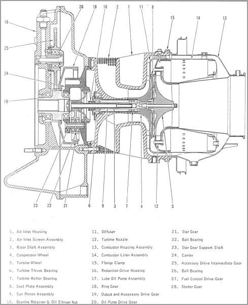
Here is a cutaway (58kb) of the engine. This is very similar to the GTP30-67 is its design, with the turbine and compressor back to back on a cantilever shaft protruding from the gearbox. The bearings for the turbine are therfore remote from the hot gas, and are cooled and lubricated by oil mist circulated up the hollow rotor shaft.
I think the time has come maybe to stop playing with the engines and put this one to work....I wonder ?
At around 100shp rating, it is tempting to consider a wheeled vehicle application for this engine. Mating single shaft turbines to wheeled vehicles is tricky. The turbine is best at constant speed, and near 100%N at that. The efficiency and output power drops off drastically at shaft speeds below the rated design speed.
Engaging a clutch manually, while attempting to keep the turbine speed constant would be fun - for a while. Maybe a bit ugly, but a belt drive constantly variable transmission (CVT) and a properly designed centrifugal clutch would be an interesting combination with this engine. After all, snowmobiles use this technology, and they are not ugly, or slow ! The engine would have to be electronically controlled still, to prevent too much droop in the shaft speed, and also to protect against turbine overtemperature.
Thanks yet again to Ian the initial information on this engine, his web site has more interesting stuff on this and many other gas turbine engines. I found the manual for this engine at Aerotecdata, they carry a large range of manuals for engines and airframes.
Microturbo Air Producer
It eventually stopped raining long enough to get it started for the first time ! Scroll to end of page)
The Microturbo Air Producer is a small single shaft gas turbine engine. There is no external shaft output, instead, the two stage axial turbine drives an oversize radial compressor. The output of the compressor is split, and around one third of the mass flow is bled off. This drives a 'cold' air turbine, which is attached to a gearbox connected to the aircraft's main engine to effect starting. (The gearbox is the one shown on the Testing and development section of the DIY turbo turbine page.)

The bad news is that the Microturbo was in pretty poor condition, as can be seen ! It has suffered from water damage, and I have a feeling that the unit may have been recovered from a damaged airframe. However, it is a fine piece, and it deserves careful restoration. The turbine 'core', i.e the compressor impeller, main bearings and two stage turbine appear to have survived untouched.

Here the unit has been stripped down as far as is possible, all the pieces cleaned and refinished, new exhaust duct (as yet untrimmed) and new fuel fittings installed.
As normal there was no starter. So, like for the Lucas APU, this part has been adapted from a motorcycle starter. It is mounted on the flange at the compressor end, and, unlike the Lucas GTS, continues to rotate with the turbine shaft during operation. Since the rotor/starter reduction ratio is only 2:1, the starter needs to be rated continuously to 25krpm. This requires that the commutator and windings are reinforced (Kevlar and epoxy), and that the rotating assembly is dynamically balanced.

Some of the oil fittings were also missing, and have been replaced using commercially available Metric Parker-Hannefin parts.
Thanks to Lee Palmer's keen eyes, a couple of extremely weather beaten Microturbo test stands came to light during a trip to an aircraft dismantlers, providing the essential parts of both the fuel and lubrication systems for this turbine. Thanks Lee, for spotting them !
Here's the identification label off one of the units:

The fuel and oil system consist of an electric combined fuel and oil pump, and a electrically operated spill valve for controlling fuel delivery to the burners.
Oil is stored in the frame mounted tank, and pumped through filters to the turbine and starter gearbox bearings. Oil pressure is maintained by a PRV in the oil pump housing. A pressure switch in the oil system illuminates a front panel lamp and releases an interlock on the starter and FSOV (fuel shut-off valve) when the oil pressure reaches the normal operating point.
Fuel is fed from an independent fuel tank via a bowl filter to the pump. Fuel pressure is maintained by a second PRV in the fuel pump housing. Fuel is fed to the burners, where the spill valve in the burner fuel return controls the percentage of fuel fed to the burners, or spilled back to the fuel tank.
Completed installation !

Combined fuel and oil pump and spill valve fuel controller:


The engine is to be controlled by a crude (but of course complicated !) analog controller (ECU). This provides sequenced starting, and eventually closed loop rotor speed control. A front panel control sets a %N1 value, and the feedback provided by a shaft speed sensor is compared with this setpoint, the controller automatically adjusting the fuelling to achieve and maintain the set speed (in theory, at least). The speed set point is backed off if the EGT exceeds a set temperature to provide acceleration control. The error signal from the control loop adjusts the PWM drive signal to the spill valve.
The engine controller will be run open loop (i.e.under manual control) initially in order to establish the characteristics of the system, to ensure the final closed loop controller will be stable.
The ECU is connected to a 12 channel  Picolog pc-based logger so that various parameters of the control system can be recorded during starting and running.
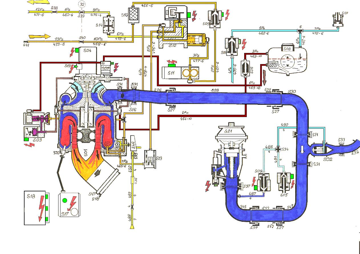
Here is a block diagram (173kb) of a typical Saphir installation, in this case from a Czech L29 trainer. (Courtesy of www.L39.com)
Friday November 24th 2000 11:55 Restored engine runs for the first time ! After some careful system testing, Ian Bennett and I set up the engine on my launch pad (correction - was launch pad, is now the wife's pergola) along with the Picologger, notebook pc, numerous video cameras and, possibly the most important item, a large fire extinguisher with the safety pin removed.
With the Picologger and video cameras running, the start button was pressed, initiating an automatic start sequence. After a short delay for oil and fuel pressure to be established, the contactor closes and the ignition and starter motor are enabled. As the shaft passes the 10% N1 mark (about 5krpm) the fuel shut off valve opens, seconds later combustion is established, and the engine continues to accelerate past 40%, where the starter motor cuts out. On the first run, as a precautionary measure, the engine was shut down 5 seconds later to look at logger traces.
Due to the long combustion delay, significant quantities of fuel had accumulated during cranking, and the logged EGT trace showed an EGT peak well in excess of 600C for 3 seconds. Subsequent starts showed much reduced combustion delay, and no EGT excursions.
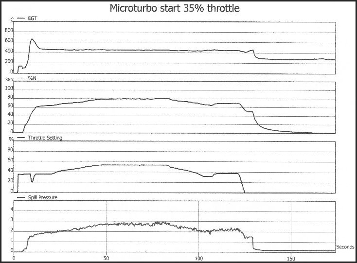
Here is a Picolog trace (69kb) of one run. It shows the EGT, % N1 shaft speed (100% N1 = 52krpm), percent throttle setting, and the pressure in the fuel spill line in bar.
At the start of the run, EGT indicates 0C until the rig is powered up. Throttle setting also jumps to 35% as power is applied. EGT jumps to 150C, since the combustor was still hot from the previous run. EGT then dips as cranking passes cooler air through. At the same time the rotor shaft accelerates from 0 to about 20%, when combustion occurs, and EGT increases to over 600C. As it passes 600C, the throttle setting is automatically backed off to about 20%, and the EGT drops back again.
Shaft speed and EGT stabilize at about 60% and 450C respectively after 15 seconds or so, then the throttle is manually wound up to 45%. The EGT actually stays fairly constant during this time, and %N increases to 80%. Sometime later the throttle is backed off, and at T+130 seconds the stop button is pressed to terminate the run.
At this stage, a lot of oil was noticed to be dripping from the starter motor, so it looks like the shaft oil seal may have failed, or that the oil pressure in the gearbox is too high due to the absence of any scavenge. However, we concluded that the tests had been pretty succesful. The engine is shatteringly noisy for such a small thing !
During the runs the bleed air from the air handling system was directed towards the exhaust end of the engine. The blast from this has to be felt to be believed, it is like a solid rod of hot metal (the compressor output is ~ 150C). The rig has no wheels fortunately, as the thrust from this output is significant, enough to cause the bleed nozzle to twist on its mounting.
Future Plans
As this engine is fitted with the airhandling accessories from the the test stands, and the plan is to use a nice air motor from a Russian Isotov helicopter engine, shown below:

This unit consists of a single stage cold air turbine, with a nominal 10:1 reduction gearbox. The power rating of this airmotor is not known, but the Microturbo air producer is known to be capable of driving a matching Microturbo airmotor to 37kW/50shp.
I learnt a lot about this engine from an Air Publication document, kindly lent to me by Ian Bennett.
Lucas Aerospace CR201 GTS/APU 
Hear the APU running (scroll to end of page).
Sunday 1st November 1998 was an memorable day for me. It was the day I received an e-mail from Chris Bennett. He'd found three Lucas GTS/APUs (Gas Turbine Starter/Auxiliary Power Unit) at an aircraft dealer's yard, and did I want in ?
For this selfless act of mateship Chris has earned my eternal gratitude. (Well, a free breakfast, at least.)
We were introduced to this particular small gas turbine unit by Ian Bennett, who has made it his life's work to acquire more gas turbines than the Smithsonian Institute (except that his machines are RUN regularly !)
The APU is attached piggy-back to the Pegasus main engine in a Harrier aircraft. It is used to provide electrical services to the aircraft when the main engine is not in use, and also to start the main engine.
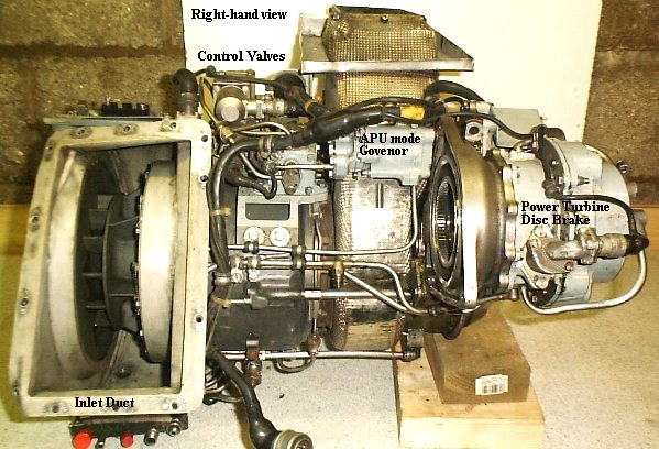
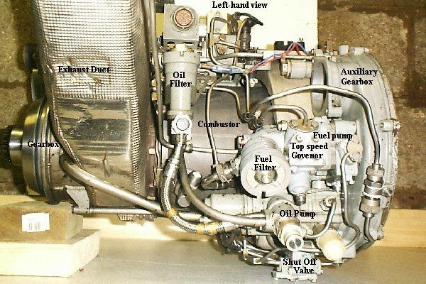
Here are left and right views of the unit 'as collected'. (Left click on the images to view larger versions ~80k)


The core 'gas generator' of the unit is a compressor/turbine arrangement similar to an auto turbocharger. This is integrated with an annular reverse flow combustor and a gearbox to provide drive for fuel and oil pumps.
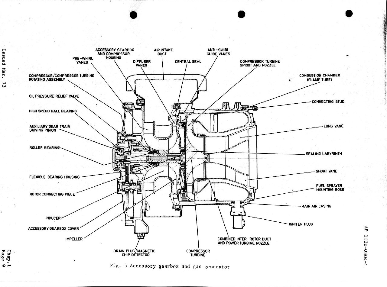
Click here to download (200k) a detailed cutaway view of the gas generator part of the unit.
The gas generator rotor is assisted to self-sustain speed by a small 24V electric motor. The exhaust gases from the gas generator assembly are expanded through an axial power turbine (see background) to drive the output shaft via a reduction gearbox and solenoid activated dog clutch assembly.
Chris Bennett and I have worked together to return these units to running condition.
The electrical equipment (alternator, starter motor and ignition unit) had been removed from these units when they were taken out of service by the RAF.
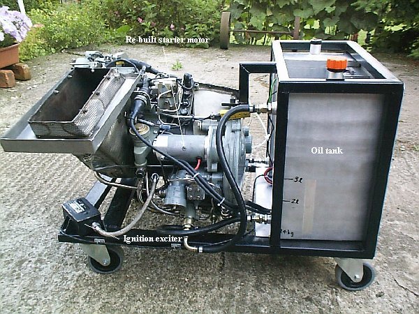
The first job then was to find an alternative starter motor, for which we chose a readily available motorcycle unit. Since this would have to run at high speed, we modified it to take ball races, reinforced the windings with Kevlar, balanced the rotor and had made a suitable splined adaptor to mate with the existing starter drive socket.
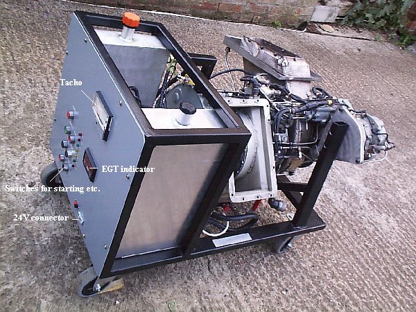
Chris Bennett welded up a nice box frame to mount the units (Great job Chris !), see the images of the completed unit below.
Fuel and oil tanks were added, to fit in the frame, and the associated piping fitted.
Instrumentation includes a tacho, EGT display and various indicators. I also decided that I would design a simple circuit to provide a 'press-to-start' function. This is entirely based on relays, and although lacking in microcontrollers has proved to work reliably !
As well as press-to-start, the control circuit allows the APU to be powered down to 'Idle' mode, so that the power turbine brake can be applied, and the power take-off dog clutch solenoids can be energised. Interlocks are provided so that the brake and dog clutch can only be selected in 'Idle' mode.
The images below show the completed APU installation.
(Click to view a more detailed image ~100kB)


Now for the noise !
If you would like to hear the unit start and shut down, click here for wav file, or here for mp3 file. (In Explorer right click, then Save As) This file is large, 1MB for the wav, 0.5MB for the mp3, 45 seconds play time, so if you download this you are truly obsessed too. If you listen carefully, you can hear the two-stage starter jump from ballasted to flat chat, followed by a leisurely ignition (around 4 seconds) and slow spool to idle. At about 15 seconds, APU mode (~70% N1 max.) is selected, and the sound recorder goes a bit deaf. At 27 seconds, the unit is shut down.
I learnt a lot about this engine from an Air Publication document, kindly lent to me by Ian Bennett. This wonderful document covers every aspect of the APU and its control system.
Garrett GTP30-67
The Garrett GTP30-67 is a small single shaft gas turbine engine. It is one member of a family of smaller gas turbines used extensively in the aerospace industry for aircraft Auxillary Power Units (APUs)and Ground Power Units (GPUs).
This particular gas turbine is buried in a very heavy (~200kg) EMU-12/E military GPU which Ian Bennett and I collected on a trip to the Netherlands.
(We sailed across the North Sea from Harwich to Hoek van Holland on the Stena 'Discovery'. This is an all-aluminium catamaran ferry, powered by four large GE LM1600/2500 aero derivative gas turbines rated at 68MW (90,000 shp) total. See these links: the builders and the operators)


Because of the difficulty in handling the GPU in this form, I have dismantled it, and installed the engine as a standalone unit in a lightweight transportable frame
Here the engine is completely removed from the aluminium housing (all 80kg of it). The 25kVA alternator has also been removed. You might ask why the alternator has been removed. Well, it adds a great deal to the installed weight, approximately 30kg, and also it generates 110V at 400 Hz. The engine has been cleaned as far as is possible, and various bits re-painted.


Here is a view of the engine re-installed in the lightweight frame. A simple front panel with RPM and EGT indicator and a couple of switches has been added.

The unit was rolled out and started on Tuesday May 25 2000. It started first attempt, and spooled up to governed speed without any fuss (well, maybe a bit of hunting by the govenor). My neighbours will be pleased, it is much quieter than the Lucas, but still satisfyingly noisy. Running under no load on the govenor, the EGT gauge reads 520F/290C.
Here is a cutaway view of the engine.

Turbocharger Turbine Project Pages
My Dad was in the Royal Air Force. He flew Vulcans in the late 50's. I think this is where my fascination with turbines came from - particularly gas turbines.
Avro Vulcan 
I used to stand at the end of the runway with these things thundering overhead.
DIY Turbocharger based gas turbine (aka DTT)
I always wanted to have a turbine of some sort, but it wasn't until I went to college and saw the Cussons educational turbine rig that I realised that one could be made without having to make the difficult bits, like the compressor and turbine, by using an automotive turbocharger.
So I set about collecting bits. This took along time. What really lit the fire was finding Kalle's DTT website.
(Place the cursor over the image for a description)
The rig consists of a frame made of 25mm steel angle gas welded together. I don't actually have any welding gear, I went to evening classes to do this bit.


These views shows the frame, on the left is the with the original combustion chamber and turbocharger. The right hand image is the current (3/98) assembly. The most noticeable difference is the combustion chamber.
LONG descriptions of the individual parts follow, and also parts that have been modified and added during development. The aim of the current development is to produce a basically 'turnkey' gas turbine 'gas generator', albeit a very inefficient one, and then to work from that base to see how far it can be developed in terms of automatic control and optimisation of ancillaries (i.e. pumps, starters etc.), and to increase the overall efficiency by using the 'waste' exhaust gas for heat recuperation, and to develop mechanical power